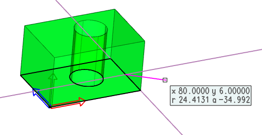
If you create a new profile further used for rotation or extrusion into 3D or if you edit an existing profile of solid, VariCAD uses 2D drawing functions at a sketching plane in 3D space. 2D drawing in 3D uses the same functions as the standard VariCAD 2D editor or 3D modeler, but they are limited only to drawing, editing or display control.
You must select the sketching plane first, if you create a new profile (see Creating 3D Solids from 2D Profiles ). Otherwise, the sketching is started whenever you want to edit the shape of a 3D basic solid or solid element (a part of Boolean tree).
The 2D profile is drawn in one color. You can switch display of objects using the following functions:
| Toggle between thick and thin outlines display in 2D |
| Switch on/off the auxiliary grid in the drawing plane |
| Toggle all 3D solids display between shaded and wire-framed |
Work with zoom, pan or view rotation or undo-redo of view changes are the same as in 3D. There are additional methods related to the 2D drawing plane:
| Define zoom by two window corners in the drawing plane |
| Drawing plane perpendicular to a view |
| Zoom all in the projected drawing plane |
| Select a center of 3D view rotation in the drawing plane |
The 2D functions are limited to drawing or editing lines, arcs, curves or points. Sketching does not support any commands working with texts, dimensions, blocks or hatches. You can use Copy and Paste; insert an existing drawing into the drawing plane or save selected objects to a file. If unsupported objects (like text objects) are inserted from another drawing, they are automatically deleted.
Auxiliary grid can be switched between sparse or dense pitch and can be switched off. By default, the grid is turned off. Some monitors, graphic adapters or combination of colors may cause grid dots less legible.
The pitch of grid is initially defined according to dimensions of edited profile. You can change the pitch in a command:
Parameters of Aux. Grid - AXGP |
Construction lines can be used the same way as in 2D mode. In sketching, it is very convenient to use temporary construction lines (leading lines) for 2D drawing of lines, multi-lines or other objects – see Temporary Construction Lines. If you create or edit a profile used for rotation, the rotation axis is displayed and is, in fact, another construction line. Standard construction lines and temporary construction lines or rotation axes are distinguished by different color.

Example of temporary construction lines in sketching. Temporary lines are at the last location entered during line drawing.
During the definition of a location in the 2D drawing plane, you can select the location in 3D space. The result is the nearest perpendicularly projected point in the drawing plane. Click the following icon in the 2D location toolbar to allow this:
| 3D location projected into the drawing plane |
You can also press the key ‘q’ or ‘!’ to allow the 3D location projection into the sketching plane.
You can also create new 2D objects (lines, arcs or curves) as an intersection of a selected 3D solid and plane:
2D Object as Solid X Sketching Plane - SXDP |
2D Object as Patch X Sketching Plane - PXDP |

|

|

|